blog · 4 August 2026
Blink without code: the 555 astable, measured
Build the classic NE555 LED blinker, predict its frequency with the datasheet formula, and check the prediction against the scope's own measurement. They agree to three digits.
Before microcontrollers, blinking an LED took one 8-pin chip, two resistors, and a capacitor, and the circuit is still the best first lesson in how time constants work. Today we build the NE555 astable in de:volt, predict its frequency on paper, and then let the oscilloscope grade our arithmetic.
The build
Open a guest session at sim.devoltapp.com and place:
- Breadboard (400) and Bench PSU at 5 V
- NE555 Timer, straddling the centre gap
- Resistor RA = 10 kΩ from pin 7 (discharge) up to 5 V
- Resistor RB = 100 kΩ from pin 7 down to pin 6 (threshold), with pin 6 tied to pin 2 (trigger)
- Electrolytic Capacitor C = 10 µF from pin 2 to ground
- A 10 nF ceramic on pin 5 to ground for decency, a Red LED plus 330 Ω from pin 3 (output) to ground, and supply wires to pins 8 and 1
The palette search finds everything by name, and pin numbers appear when you hover the chip. Press Run and the LED settles into a slow, confident blink.
Predict, then measure
The astable's datasheet formula:
f = 1.44 / ((RA + 2·RB) · C)
With our values: 1.44 / ((10k + 200k) · 10 µF) = 1.44 / 2.1 = 0.686 Hz, with a high-side duty of (RA + RB) / (RA + 2·RB) = 52.4%.
Now make the scope check it. Open the Analysis panel; the interesting channels are the capacitor node and the output node. Set TIME to 5 s so several cycles fit in the window, open the display-settings menu, and switch on Measurements. On our bench the strip read:
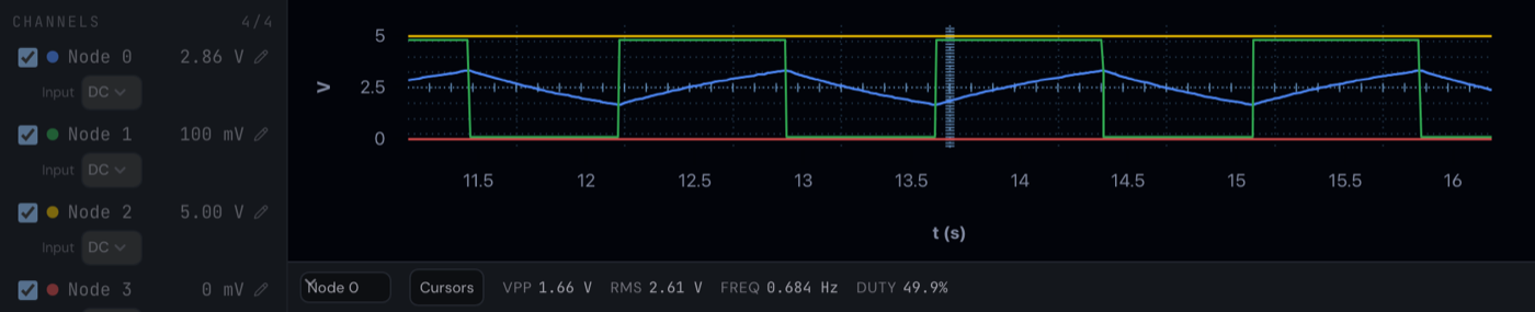
FREQ 0.684 Hz against a predicted 0.686 Hz: agreement to a third of a percent, and the difference is real physics rather than sloppiness, since the formula's 1.44 is itself an approximation. VPP on the capacitor node reads 1.66 V, which is exactly the ⅓ Vcc to ⅔ Vcc excursion the 555's comparators enforce: the entire mechanism of the oscillator, visible as one number.
Watch the shape too. The capacitor trace is a shark-fin: an RC charge curve through RA + RB, then a faster discharge through RB alone. That asymmetry is why the plain astable cannot reach 50% duty, and why our high side runs longer than our low side.
Two honest instrument notes
If FREQ reads Unavailable on a shorter time window, that is the measurement engine being truthful: with fewer than a couple of full cycles in view, it declines to guess. Give it a longer window. And note the sample-rate line above the plot: acquisition happens inside the solver at up to 10 kSa/s, and the instrument reports the effective rate it achieved rather than pretending.
Make it yours
Everything is live while the simulation runs. Drop C to 1 µF and the blink becomes a 6.9 Hz flutter. Swap the LED for the 8 Ohm Speaker part, push the frequency into the hundreds of hertz, and the astable becomes a tone generator (wire a real loop; since July the audio path needs both legs connected, like hardware). Push RB down toward 1 kΩ and watch the duty cycle climb, then check your reasoning against the formula.
The monostable cousin of this circuit, a button-triggered timer, is coming later this week. The 555's full pin behaviour, including the control-voltage input we decoupled and ignored, lives at docs.devoltapp.com/parts/timer-555.