blog · 1 August 2026
Your first circuit: an LED that doesn't die
Build the classic LED-plus-resistor circuit in the simulator, size the resistor with one line of arithmetic, and then burn out a spare on purpose to see why the resistor matters.
Every electronics course starts with an LED and a resistor, because it is the smallest circuit that can go wrong in an instructive way. In de:volt you can build it in two minutes, measure it honestly, and then do the thing your teacher would never allow: leave the resistor out and watch what happens.
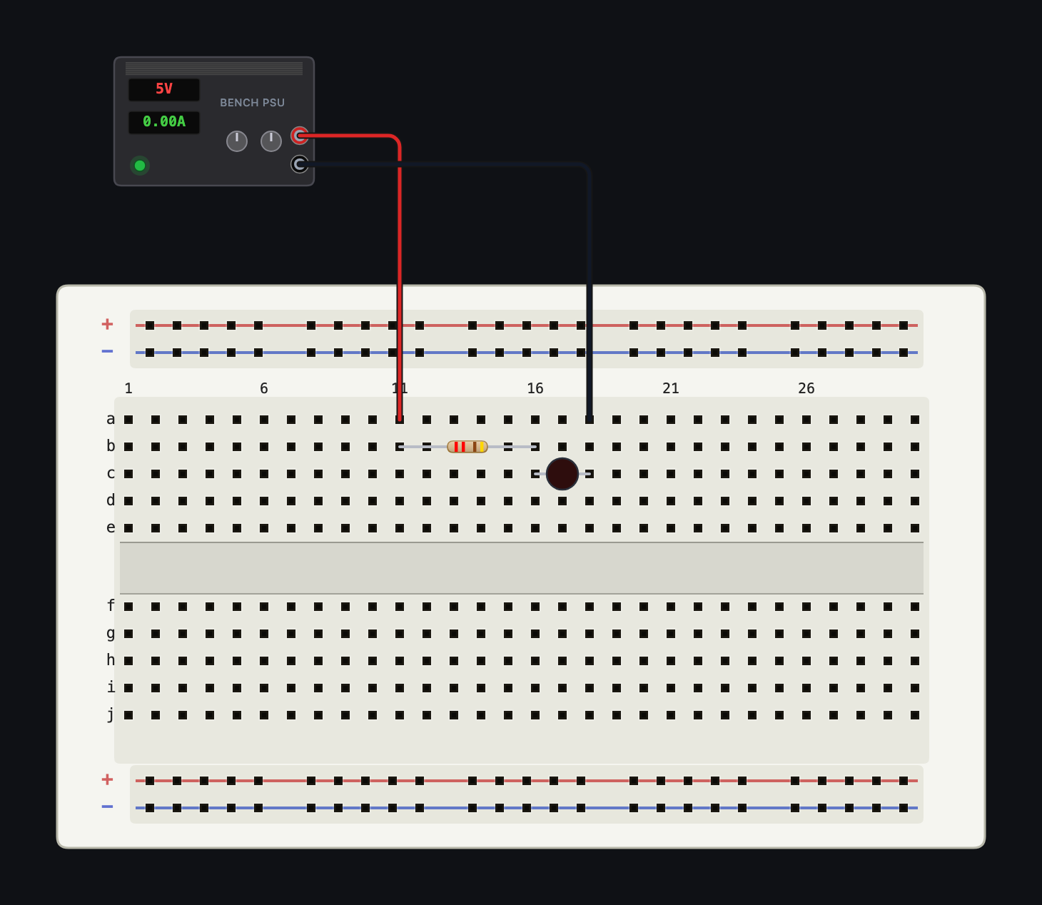
Build it
Open sim.devoltapp.com; a guest session is fine. Then:
- In the Components palette, add a Breadboard (400) and a Bench PSU. The PSU defaults to 5 V, which is what we want.
- Add a Resistor. Drop it on the top bank of the board so its legs land in two columns a few holes apart. Select it and set its value to 220 Ω with the value chips in the Inspector.
- Add a Red LED. Place its anode in the same column as the resistor's right leg. Hover a leg if you are unsure which side is which: since July, polarized parts show a green + and a red − chip above their legs, and the board art paints a flat bar on the cathode side.
- Wire the PSU's red terminal to the resistor's free leg, and the LED's cathode to the PSU's black terminal. Click a pin, then click the destination, and the wire routes itself.
- Press Run. The LED lights, and the PSU's current readout settles near 15 mA.
That number is not a stage prop. Probe the circuit and the engine's solved answer comes apart cleanly: the red LED drops 1.78 V, the resistor takes the remaining 3.22 V, and 3.22 V across 220 Ω is 14.6 mA by Ohm's law. Drag the multimeter probes (View → Multimeter) across the LED and you will read the forward drop directly.
The arithmetic, once
The series resistor exists to set that current. The formula is one subtraction and one division:
R = (Vsupply − Vf) / I
For a 5 V supply, a 1.8 V red LED, and a target of 15 mA: (5 − 1.8) / 0.015 ≈ 213 Ω, so the nearest standard value of 220 Ω is the classroom default. Want it dimmer and cooler? 470 Ω gives you 6.8 mA. Different colour? Select the LED and pick a swatch in the Inspector: colour and forward voltage change together, since a blue LED sits at 3.0 V and a white one at 3.2 V, and the same formula still answers.
Now break it, on purpose
Duplicate your circuit (Edit → Duplicate on a selection works, or just build a second copy further down the board) and this time connect the LED straight across the supply with no resistor. Run it.
The simulator does not shrug. The Diagnostics tab raises an LED overcurrent warning, and the LED does more than glow brighter: damage in de:volt accumulates like real damage, severe overloads destroy the part quickly, and a dead LED stays dead until you reset it. Since the July physics work, the check is magnitude-based too, so a token 1 Ω resistor on a 12 V supply is correctly treated as no protection at all rather than passing on a technicality.
This is the honest version of the lesson. A real 20 mA LED on a real 5 V rail draws whatever the diode equation says it draws, which is far too much, briefly.
Read the numbers, not just the glow
Two habits worth starting on day one. First, open the Analysis panel and tick the LED's node in the channel list; a flat 3.22 V trace with the scope's honest sample-rate readout above it beats guessing. Second, click through the LED's Datasheet tab in the Inspector. Every part in de:volt carries one, including a disclosure of what the model does and does not include, so you know what you are trusting.
The same circuit is the first lesson of the free intro course at learn.devoltapp.com, with objectives that check your work and tell you the actual measured value when something misses. Tomorrow: what pull-up resistors are for, and why buttons lie without them.