blog · 11 August 2026
The micro:bit meets the breadboard: external LEDs and the 3.3 V rules
Wire the micro:bit's P0 to a real LED on a real breadboard, blink it from MicroPython, and add the breakout board when three pins stop being enough.
The micro:bit's LED matrix is a lovely self-contained world, and the whole point of the edge pads is to leave it. Today the board drives an external LED on a breadboard, which is the moment MicroPython stops being screen output and starts being electronics.
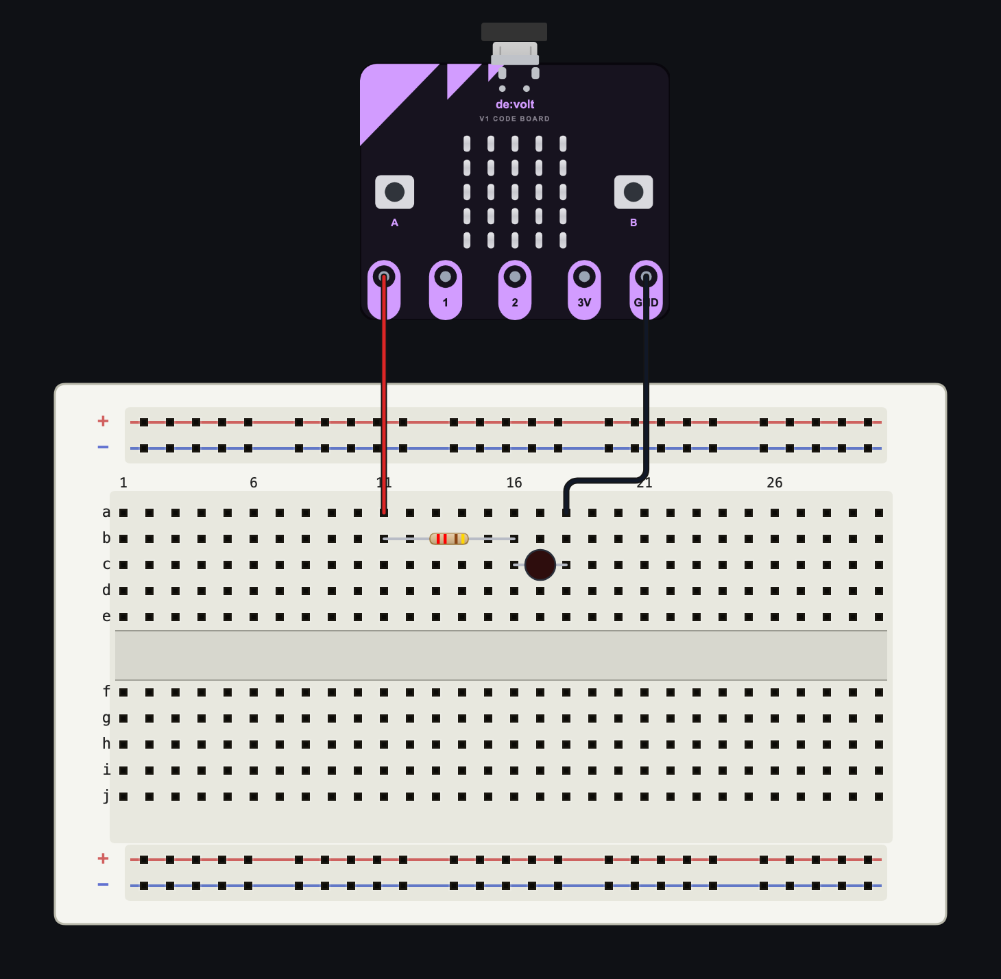
The wiring
- Place a Breadboard (400) and a BBC micro:bit V1 beside it. The board is a workspace part; it sits next to the breadboard and reaches it with wires from its five edge pads: 0, 1, 2, 3V, GND.
- Put a 220 Ω Resistor on the board's top bank, and a Red LED with its anode sharing the resistor's right-hand column, cathode a column further along.
- Wire pad 0 to the resistor's free leg, and the LED's cathode to the board's GND pad. Two wires, total.
- Select the board, open the Code tab, and run:
from microbit import *

while True:
    pin0.write_digital(1)
    sleep(500)
    pin0.write_digital(0)
    sleep(500)
The breadboard LED blinks at 1 Hz. Put the scope on the P0 node and you get a textbook 3.3 V square wave; the write really does drive the net, and the net really does feed the diode equation that lights the LED.
The 3.3 V rules
Three facts keep simulated builds transferable to the physical kit box:
- The micro:bit is a 3.3 V device. P0 high is 3.3 V, not 5 V, so a red LED at 1.8 V forward drop across a 220 Ω resistor draws about 7 mA: visibly lit, comfortably safe. Blue LEDs sit at 3.0 V and white at 3.2 V, so from a 3.3 V pin they barely turn on; try one and watch the current round to almost nothing. That is the diode equation doing its job, not a simulator shortcut, and the same experiment on hardware disappoints in exactly the same way.
- Current is a budget, not a suggestion. A real V1 pad is only good for a few milliamps, so the habit of a proper series resistor per LED is not negotiable, and the simulator's diagnostics call out a missing or token one.
- Common ground is everything. The LED circuit only works because its cathode returns to the micro:bit's own GND. Delete that wire and watch the LED die and the P0 trace turn strange; every multi-board mess in every classroom is this wire, missing.
The 3V pad deserves a mention: it can power a small rail (sensors, a second LED chain) whenever the board itself is powered, and clicking the on-canvas USB connector cuts and restores everything at once, which is a satisfyingly physical way to demonstrate "where does the energy come from".
Reading pins works too
The pads are bidirectional. Wire a Push Button from pad 1 to GND... and pause, because you know this one now: on a bare micro:bit V1, pin1.read_digital() on an unwired pin floats. Give it a pull-up (10 kΩ from pad 1 to the 3V pad) and read it:
from microbit import *

while True:
    if pin1.read_digital() == 0:
        display.show(Image.ARROW_S)
    else:
        display.clear()
    sleep(50)
Hold the button and the matrix answers. read_analog() does the same trick with a potentiometer wiper, 0 to 1023 across 0 to 3.3 V.
When three pins run out
Real projects hit the pad ceiling fast, and the fix ships in the box: select the board and switch on Breakout board in the Inspector. The board docks into an edge-connector breakout and gains P8, P12, P13, P14, P15, and P16 in one pad row, digital-only exactly as the V1 hardware exposes them. Existing wires stay put, and the toggle refuses to undock while anything is still wired to a breakout-only pad, so you cannot strand a circuit by accident.
The pad-by-pad reference, including which APIs each pin supports, is at docs.devoltapp.com/parts/microbit. Tomorrow: the HC-SR04 ultrasonic sensor, measured in microseconds.