blog · 15 August 2026
The RP2040's ADC reads the knob: analog in, PWM out
Wire a potentiometer to ADC0, read it with MicroPython's read_u16, and close the loop with PWM brightness on an LED. Twelve real bits, honestly scaled.
Digital pins answer yes or no; the ADC answers "how much". Today's build closes the analog loop on the RP2040 MicroPython Board: a potentiometer sets a voltage, ADC(26) reads it, and PWM turns the number back into LED brightness. It is the hello-world of every sensor project you will ever build, because a thermistor, an LDR, or a joystick is just this circuit with a different divider.
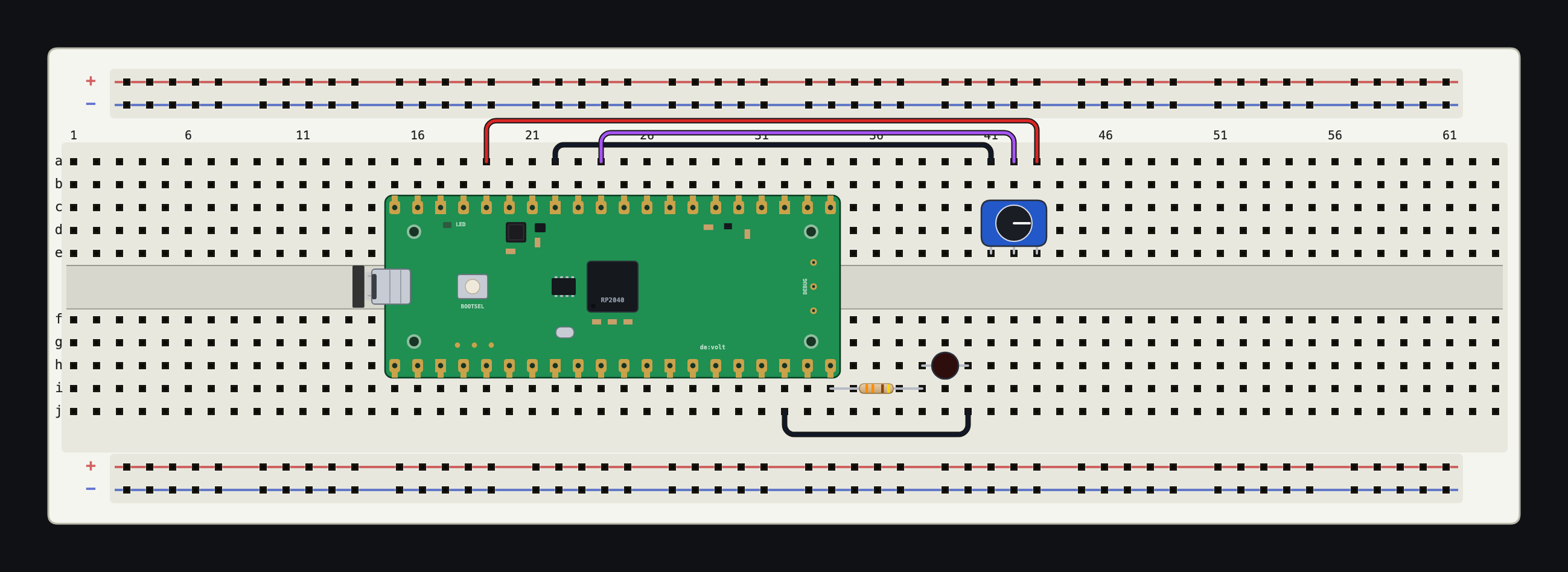
The wiring
At sim.devoltapp.com, on a Breadboard (830) with an RP2040 MicroPython Board straddling the gap:
- Potentiometer in free columns. Wire one track end to the board's 3V3 pin, the other end to AGND (the analog ground pin exists for exactly this), and the wiper to GP26, which is ADC0.
- The output stage from last week: GP15 to a 330 Ω Resistor to a Red LED, cathode to a GND pad.
- Select the board, open Code, and run:
from machine import ADC, Pin, PWM
import time

pot = ADC(26)
led = PWM(Pin(15))
led.freq(1000)

while True:
    led.duty_u16(pot.read_u16())
    time.sleep_ms(20)
Drag the potentiometer's knob. The LED follows it: dark at one end, full brightness at the other, smooth in between. Twenty lines shorter than any explanation of what an ADC is.
What read_u16 actually returns
The RP2040's converter is 12-bit, so it distinguishes 4,096 levels between 0 V and its reference. MicroPython's read_u16() presents that as a 0 to 65,535 value for API consistency across boards; the low bits are scaling, not new information. The simulator models the conversion honestly (the emulation runs the real firmware against a real solved node voltage), so at half travel you get about 32,700, and the arithmetic 3.3 V × value ÷ 65,535 recovers the wiper voltage the multimeter shows you.
The loop feeds that number straight into duty_u16, which is why the code is so short: both ends of the pipe speak the same 16-bit dialect. The LED's apparent brightness will not feel linear (your eye is logarithmic, as the potentiometer post discussed), and squaring the value before writing it is the classic one-line fix worth trying live.
Watch the PWM with the scope
Tick the GP15 node in the Analysis panel, trigger on a rising edge, and set a 5 ms window: a clean 1 kHz square wave whose duty tracks the knob. Turn on Measurements and the DUTY readout follows your hand. This is also the moment to appreciate what "PWM brightness" means: the LED is fully on or fully off thousands of times a second, and the knob is adjusting the ratio, not the current. The scope makes that argument better than any paragraph.
Two RP2040 ADC notes for when you leave the simulator: GP26, GP27, and GP28 are the ADC-capable pins (the simulator's diagnostics will remind you if the others are asked to float), and the converter reads against the board's 3.3 V domain, so a 5 V sensor output needs a divider first, on the bench as here, because the pins are not 5 V tolerant.
The same pattern, other sensors
Replace the potentiometer with a divider made of a fixed resistor and the catalog's LDR and the code reads light; use the Thermistor (NTC) and it reads temperature, with the Environment panel's sliders standing in for the sun and the weather. Both parts show their live resistance in the Inspector, so you can sanity-check the divider maths before the code touches it. The environment story, including self-heating and why the thermistor is not quite at room temperature, is later this week.
Board reference: docs.devoltapp.com/parts/raspberry-pi-pico. Tomorrow: nodes, highlighting, and labels, the tools that keep a growing board legible.