blog · 6 August 2026
RP2040 MicroPython: a button, an LED, and a pull-up you can probe
Wire a button and LED to the RP2040 MicroPython Board, write ten lines of machine.Pin code, and put the scope on the internal pull-up to see why the logic reads backwards.
Yesterday's post covered why floating inputs lie. Today we let a microcontroller solve it for us: the RP2040 MicroPython Board's internal pull-up, enabled in one argument, visible on the scope like any other resistor. This is the "hello, GPIO" build for the board, and everything in it runs on the free plan.
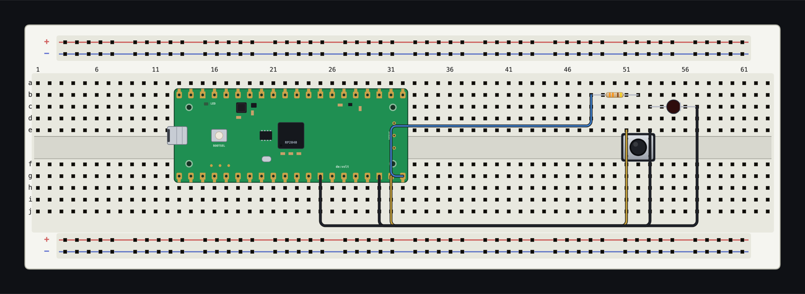
The build
- Open sim.devoltapp.com, place a Breadboard (830), and drop an RP2040 MicroPython Board onto it so it straddles the centre gap. The pin labels sit along both edges; USB power is on by default, so the 3V3 pin is live.
- Place a Resistor (330 Ω) and a Red LED in free columns, chained as usual: GP15 to resistor, resistor to LED anode, LED cathode to any GND pad on the board.
- Place a Push Button straddling the gap. Wire one side to GP14 and the other side to a GND pad. No external pull-up on purpose.
- Select the board, open the Code tab, and run:
from machine import Pin
import time

led = Pin(15, Pin.OUT)
button = Pin(14, Pin.IN, Pin.PULL_UP)

while True:
    led.value(0 if button.value() else 1)
    time.sleep_ms(20)
Click and hold the button on the canvas: the LED lights while you hold it. Release, and it goes dark.
Why the logic reads backwards
button.value() is 1 when nobody is touching anything. That surprises every beginner, and the scope makes it stop being surprising. Tick the GP14 node in the Analysis panel: it idles at 3.3 V, because Pin.PULL_UP connected a real internal resistor from the pin to the 3.3 V rail inside the simulation. Press, and the button shorts the pin to ground: the trace steps cleanly to 0 V. So pressed reads 0, released reads 1, and the code inverts it back with 0 if button.value() else 1.
This is not UI theatre. Before July the internal pulls were unmodelled and this exact circuit read close to 0 V at idle; now the pull-up is a resistor the solver stamps like any other. Delete the Pin.PULL_UP argument, rerun, and the Diagnostics tab raises a floating-input warning on GP14 while the LED behaviour turns unreliable. Put the argument back and the warning clears. One argument, one resistor, one honest lesson.
While you are in Diagnostics you may notice warnings about GP26, GP27, and GP28 floating. That is the simulator being conscientious about the unconnected ADC-capable pins; wire them or ignore them, but it tells you either way.
Speed, stated plainly
An RP2040 emulation executes your actual compiled MicroPython, and that costs real computation. On a modest laptop, a busy RP2040 circuit can run slower than real time, and the toolbar status pill will say slow with an explanation rather than letting time stretch silently. For a button-and-LED lesson it is irrelevant (a 20 ms poll loop survives any slowdown), but it is worth knowing before you build a classroom exercise that depends on wall-clock timing. The SPEED control can also deliberately slow a circuit down, which turns out to be a feature when you want to watch fast events at human pace.
Where to take it
Three one-line upgrades, in rising order of fun: swap led.value() for PWM(Pin(15)) and fade instead of switch; move the button handler to button.irq() and discuss debouncing while the scope shows you the bounce the simulated tact switch faithfully lacks; or wire a second LED on GP16 and build a two-state traffic light. The board's full pinout, powering rules, and the ADC pins we conspicuously did not touch today are documented at docs.devoltapp.com/parts/raspberry-pi-pico.
The ADC gets its own post next week: a potentiometer on GP26, and brightness that follows the knob.